Recovering from fIELD dAY, David HK1A (K1KK) and myself decided to work the CQ WW VHF on 2 & 6 meter contest this week end. Problem number 1 was that the “Man Cave” was in a mess after FD and we needed to make room for a second station, one on HF and the other on VHF/UHF. Problem #2 was that I have only the usual 2 meter whip on my car and no serious 2 or 6 meter antennas. This is a real problem… back to antenna design and testing. It helped that we did not realize that we were a week early and the contest is next week end thus giving us a few days to prepare.

Thinking about antenna design 
Scratch pad on 6m vertical Yagi
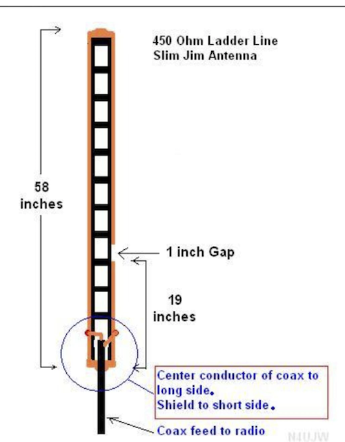
Thinking about 2 meters, David made a “Slim Jim” antenna out of ladder line and we hoisted it up to 20 feet elevation on a pole. Testing it showed that we reached repeaters in Moorehead city, Raleigh, Currituck, Franklinton and repeaters in many other counties. About 75 mile radius centered in Falkland, NC. This blew my mind as I viewed 2 meters as a HT and local repeater mode only, not a wider area capable of hitting stations and repeaters in a large circle with just a home made antenna. Here is a J-pole calculator for this antenna, use a velocity factor of 0.92. Now, this should be in everyone’s go bag for emergencies.

Slim Jim 2 Meter antenna on a halyard 
Next we assembled a 6 meter horizontal 5 element LFA yagi on a pole. The band was not terribly active but we did make a half dozen FT8 contacts. It was interesting to see the signals as we rotated it by hand into the different directions.

The next antenna to be set up was a 6 element 2 meter LFA yagi on a 7′ boom on a pole about 18 feet up in the air. Horizontal polarization is best for DX, not repeaters. It was tuned on 144.200 MHz and called CQ. Here is a reference to free yagi designs by G0KSC.

The vertical beam antenna for 6 meters was constructed out of army tent poles and 5 strips of wire. It seemed to be quieter than the 6 meter horizonal yagi. Contact was made into Minnesota. Lengths (left to right on diagram) are:
| Reflector | 114.96″ |
| Driven element (J-Pole) | adjust to resonance |
| Director #1 | 104.2″ |
| Director #2 | 102.1″ |
| Director #3 | 102.1″ |
Spacing is 4′ between all elements. The first and last elements are taped to the non conductive poles. The driven element is a J-pole made from 450 ohm line 1/4 wave matching stub (51.5″) end feeding a 1/2 wave radiator (111.9″). Connection of the coax feed line (through a 1:1 balun) to the stub is about 3.5″ from the shorted end of the stub.
Next came the “Bi Quad” 2 meter antenna made out of strips 1″ galvanized steel straps shaped into two squares touching at the tips of the square. It needs a reflector about 7″ behind the straps consisting of a 7′ square of “chicken wire”. The connection point was made out of 1″ PVC pipe with a SO-239 mounted on it. More runs to Lowe’s for more PVC pipe and wire. Normally a square quad has an impedance of about 120 ohm, when two are connected in parallel the impedance drops to 50-60 ohm. The reflector makes the bi-directional quads into a directional antenna with 15 dBi gain. See Bi-Quad Antenna Calculator. This antenna is very forgiving on the dimensions and and is very popular for higher frequencies above 144 MHz (2 meter).
More to come after the reflector is done and we test it in the contest!
73 David HK1A & Peter N4PVH.


One thought on “Antenna Fun!”