
The Project
Initial Start of a Super Station
The Brightleaf Amateur Radio Club in Greenville, NC has been selected by Voice Of America to be one of the three special event stations using the special call sign “W4A” to celebrate the 80th anniversary of the first transmission from the VOA. The three special event stations will be “W3V“, “W8O” and “W4A” spelling out “VOA“. In preparation for the special event on February 19-20, 2022 it was thought it would be fitting to use the four approximately 1000’ rhombic antennas at VOA site C outside Greenville for this event. The site has been decommissioned since the 1980’s and now East Carolina University (ECU) is in control of the site and use it for other purposes. The club has for decades run temporary ladder line feeds to the rhombic antennas for all kinds of special events at our cost.
Recently however, these feed lines were torn down by maintenance crews of the site as well as we have lost some of the telephone poles supporting the feed lines. We need to repair the lines and bring them back to the building by planting new telephone poles to get the height high enough not to be torn down by passing equipment. We have the maintenance crew of VOA site B ready to repair the antennas but have no funding for this adventure.
This brings up the potential to realize that this could be much more than just an occasional special event station. The four rhombic antennas and two rotatable log periodic antennas could be reconnected to the building and set up a permanent Amateur Radio Station that could reach out and touch most of the world with these antennas. During hurricanes and other natural disasters it could be an emergency communication hub. It could also be a remote station for those that cannot have antennas due to HOA’s or other reasons. There is a 100’ tower that could be used for digital modes (mesh network) extending over the entire region. There is high speed internet to the building already. The potential of the site to grow amateur radio activities is extremely large. It would be a waste to allow all of this to rot away and not use it.
To this end we are meeting with ECU and the managers from our local VOA to evaluate what it would take to do the repairs. Once that has been evaluated then an estimate of the cost of the repairs will follow. Once that is done, then evaluation of how to turn this site into a world class amateur radio station will follow. We will then apply for grants to be able to accomplish these lofty goals.
As background information, the Brightleaf Amateur Radio Club was founded in 1967 and has been continuously active since then. We are a 501(c)(3) organization and currently I am the president for 2021 & 2022. Visit our club web page (https://w4amc.com) to see the kinds of activities we have been supporting. We are involved with education of over 100 marines at Cherry Point to get their amateur radio licenses in the last two years. This is seen as a necessary skill for their communication specialists. In the year 2000, our club and ECU used these VOA antennas to participate in RIMPAC exercise to provide medical support to the armed forces camp in Hawaii (http://archives.starbulletin.com/2000/06/15/news/story2.html).
I look forward to any help and advice to help get this project off the ground. Funding is going to be needed. Please donate here. This page will be updated as things happen, so stay tuned.
UPDATE: We have had a severe loss in or family and the project has been on hold. We will restart it in 2023.
Sincerely, Peter N4PVH (info@w1voa.com)
UPDATES TO THE PROJECT WILL APPEAR BELOW:
Station Design
12/28/2021: Using Zoom, we discussed the elements of making this site a super station. The video is about an hour long and very in depth. We thank David De Coons, WO2X, for his advice and experience and look forward to his help automating the station.
Thanks, Peter N4PVH.
Desired Features of the Station
- 3-6 work stations with computers and radios
- Switching of antennas (remote controlled)
- Band Filters for stations/bands
- Lightning protection outside the building
- Baluns 9:1 to go from 530 ohm to 50 ohm on rhombic antennas
- Computer controlled rotors for log periodic antennas
- Node-Red software control of stations to allow remote control w any browser
- Generator back up power (the whole building is backed up)
- High speed internet (Fiber optic cable is already at the building)
- Feed lines that cross roads have easy to disconnect breaks to allow large vehicles
- Create a handiham remote interface using a touch screen with a grid on it.
Here is an initial RF Path from the antennas to the radios:
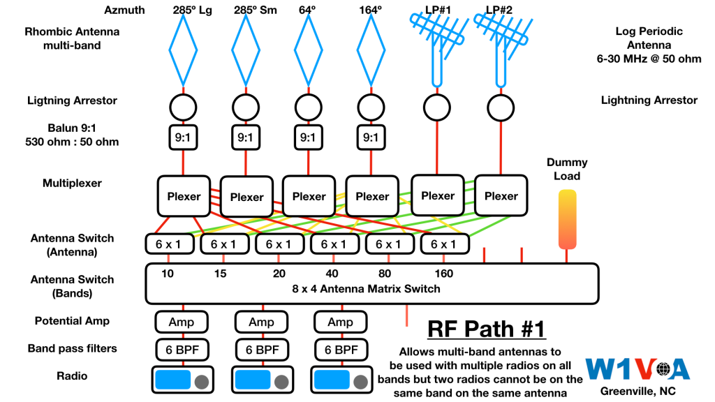
A more simple station set up below but this has only one radio per antenna. Multiple radios can be on the same band but different antennas with the local interference problems that this generates.

Performance Test of the Antennas
In 2018, David HK1A drove his car under the feed line of one of the rhombic antennas, climbed a ladder and connected his 100 watt transceiver to the antenna and did the CQ WPX-CW Contest from his car. Here is how he did:


Congratulations David HK1A for quite a win and dedication to patch the broken feed lines and only 100 watts! This is why we are getting excited about this project! 73 Peter.
The Site “C” Tour
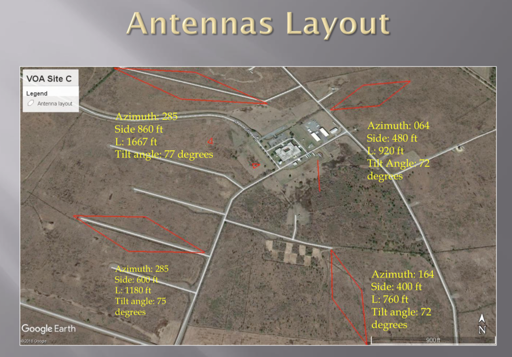
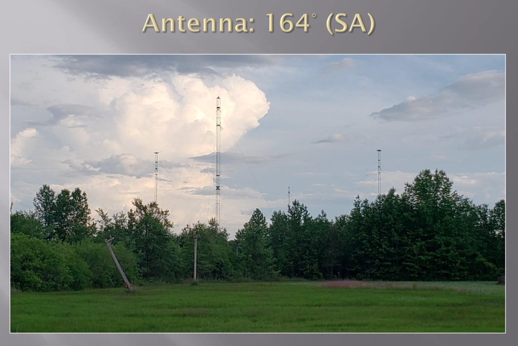
This site was the listening station hearing the transmissions from the rest of the world so the antennas are optimised for listening as they never transmitted from here. We intend only to use up to the amateur legal limit but most of the time 100 watts will sound like 10,000 watts due to the approx. 19-23 dB gain that the four approximately 1000′ long rhombics can attain. There used to be 23 antennas in all directions but now only 6 remain. The other two antennas are rotatable log periodic that match 50 ohm from 4 mHz through 30 mHz with 13 dB gain. These need updated hardware and control software to have computer control of the rotation.
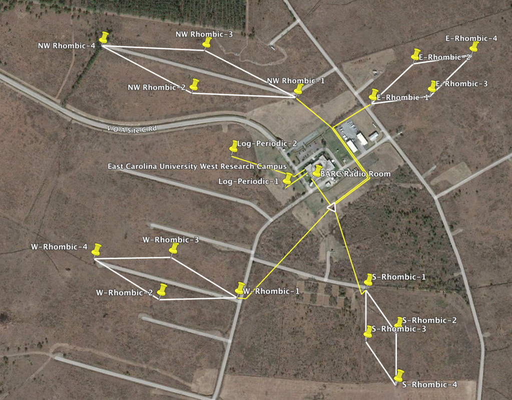
Large Rhombic Antennas
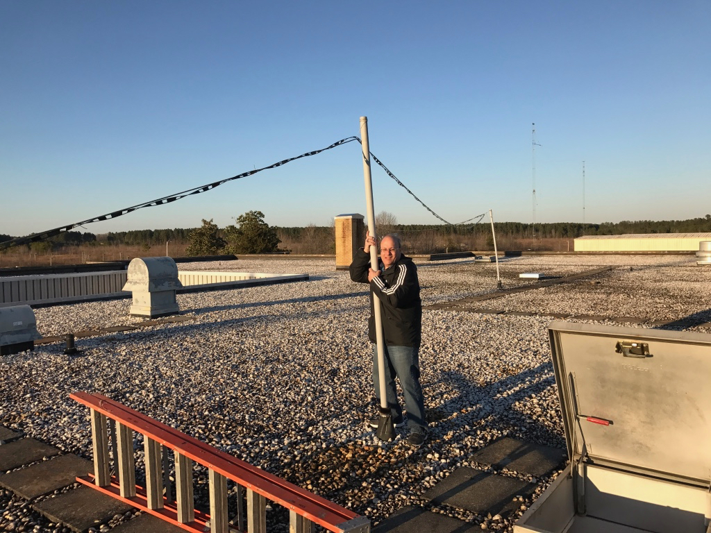
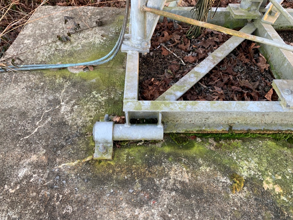
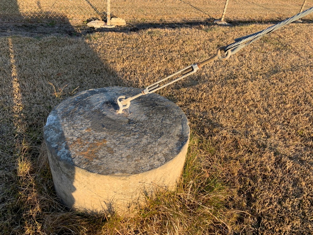
There are four remaining rhombic antennas that have 3 wires on each side. There is no terminating resistor at the end therefore are bidirectional. The tower structure and the three wire active elements are intact. The vertical portion of the feed lines are intact but have minor damage. The problem is from the vertical feed point back to the building, they are partially there or missing wires. Telephone poles have rotted and are hanging by the feed wires. There is about a mile of feed lines to the antennas, needing about 60 telephone poles (Class 4 25′ CCA treated) and 4 gauge hard drawn copper wire needed to run new feed lines to the antennas.


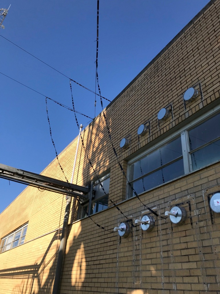
Next, getting them into the building poses a new problem as the antennas used as a listening function could run the lines underground into the building. As transmission of RF energy, they should not be buried underground and we will have to set up a new way to get them in.


Rotatable Log Periodic Antennas
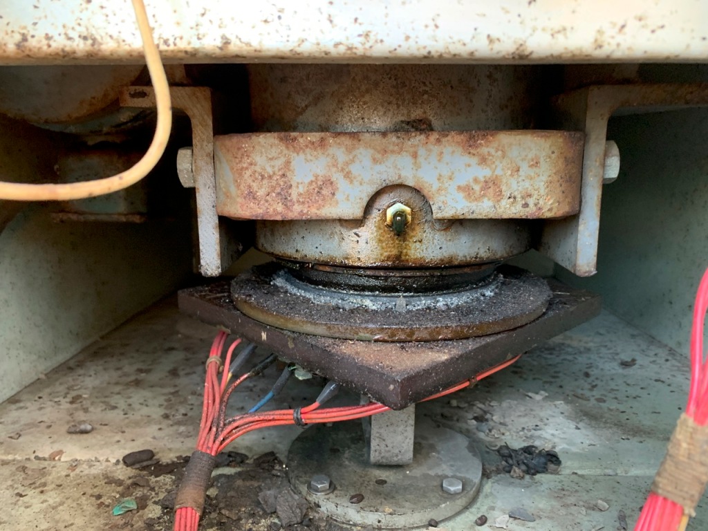
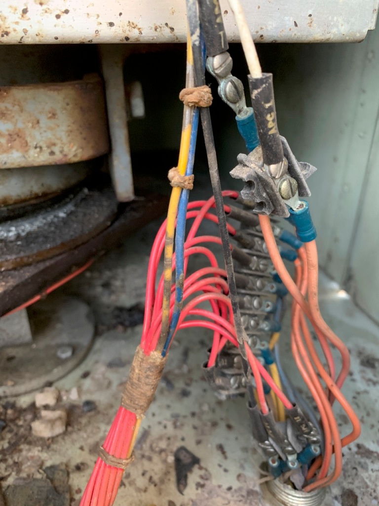
The two Rotatable Log Periodic antennas need to be refurbished as the feed lines and control wires will need to be changed as the new equipment is computer controlled and new design. the antennas themselves look good but will need to be inspected for safety reasons. The power, control lines and coaxial cables will need to be replaced. New controllers are needed.


Tower for Digital/Repeater Use
There is an approx. 150′ tower outside the ham shack that has one 2m/70cm antenna at the top and non functional microwave dishes. This used to be used a digipeater for the area for Winlink. The radio is defunct. Now ideas of a mesh network or other local communication mode is being thought of. Ideas anyone?

30′ Satellite Dish
This would take some thinking about what this could be used for, EME? It would take some resources to reactivate it. Thoughts?


So, there is the quick tour of the site. Big plans are underway but will take a lot of manpower and funding to get this done. Any ideas, comments or donations are gladly accepted. We will be interviewed about this at the QSO Today Expo March 12-13, 2022 by Eric Guth 4Z1UG.
Stay tuned for the 80th anniversary of the first transmission from VOA, the special event is February 19-20, 2022 and see if you can contact all three stations on CW/SSB/Digital modes. Check out the VOA Museum in Ohio for more information. The interview about the 80th anniversary will be on Ham Nation on Feb. 16, 2022 at 9PM (Eastern). Other talks and interviews are being scheduled.
Internet Articles about VOA:
A tour of VOA Site B in Greenville, NC:
https://swling.com/blog/2012/12/for-your-holiday-enjoyment-a-tour-of-the-edward-r-murrow-transmitting-station/
VOA Site C and towers of NC:
https://www.fybush.com/site-030724.html
ECU Western Research Campus (Formerly VOA site C):
https://east.ecu.edu/2021/06/16/going-west/
Stopping points in NC:
https://www.stoppingpoints.com/north-carolina/sights.cgi?marker=Voice+Of+America&cnty=Pitt
VOA News online:
https://www.voanews.com/


Wonderful project! Congratulations!
I regret very much to live so far from this site, I would have participated with great pleasure in its development!
I wish you full success for the continuation.
Best 73 de HB9ONN
By the way the whole purpose of making it remote control is so that you could access it remotely from wherever you are through the Internet. Stay tuned, you still may be able to use the antennas. 73 Peter
LikeLike
I have used both 450 ohm ladder line and 600 ohm open wire feed-line. I doubt that 450 ohm ladder line using a plastic spacer existed before or during WWII. 600 ohm open wire feed-line is very low tech and does not require any special materials or any special manufacturing technology. All 600 ohm open wire feed-line requires is 2 wires with a spacer at regular intervals to separate the 2 wires. 600 ohm open wire feed-line is extremely easy to make and extremely easy to build. I am not sure plastic was available to make 450 ohm ladder line before or during WWII. The other issue is when rain, ice, or snow are on the plastic spacer used in 450 ohm ladder line , that can create large changes in the impedance of the feed-line, and will require the antenna tuner, or transmitter loading circuit to be adjusted. Adjust an antenna tuner, or a transmitter load circuit, is not trivial when you are dealing with tens of thousands of watts of power used by VOA. Rain, Snow, and Ice have nothing to adhere to in the space between the 2 wires in 600 ohm open wire feed-line, so there are no impedance changes during rain, snow, or ice. The space between the 2 wires in 600 ohm wire feed-line is only air, so there is nothing for rain, snow, or ice to stick to, to change the feed-line impedance. There are many myths about the difficulty of running 600 ohm open wire feed line. I would guess that the original feed line at the VOA before and during WWII was 600 ohm open wire feed line, since I doubt plastic and plastic manufacturing techniques may not have been available until after WWII.
LikeLiked by 1 person